Yoto Optoelectronics Technology Co., Ltd. is a high-tech enterprise focused on infrared optical technology. Adhering to the philosophy of "Empowering Precision with Technology, Leading the Future with Innovation," the company is dedicated to the research, development, production, and sales of infrared thermal imaging, night vision technology, and optoelectronic equipment. With years of technical expertise and market expansion, we have become a leading supplier of infrared sights and cameras in China, with products widely used in national defense, law enforcement, outdoor hunting, security surveillance, and industrial inspection.
Our Infrared sight is a low-cost, modular night vision viewing equipment, imaging by the temperature difference between the target and the background, using a manual focusing optical system, and the optical lens can be changed quickly; It can be adapted to a variety of rifles through the lens gun connecting seat, which is used for viewing individual personnel targets within 400~1300 meters throughout the day. Laser ranging function can be optional. It has the characteristics of all-day, light weight and convenient operation.
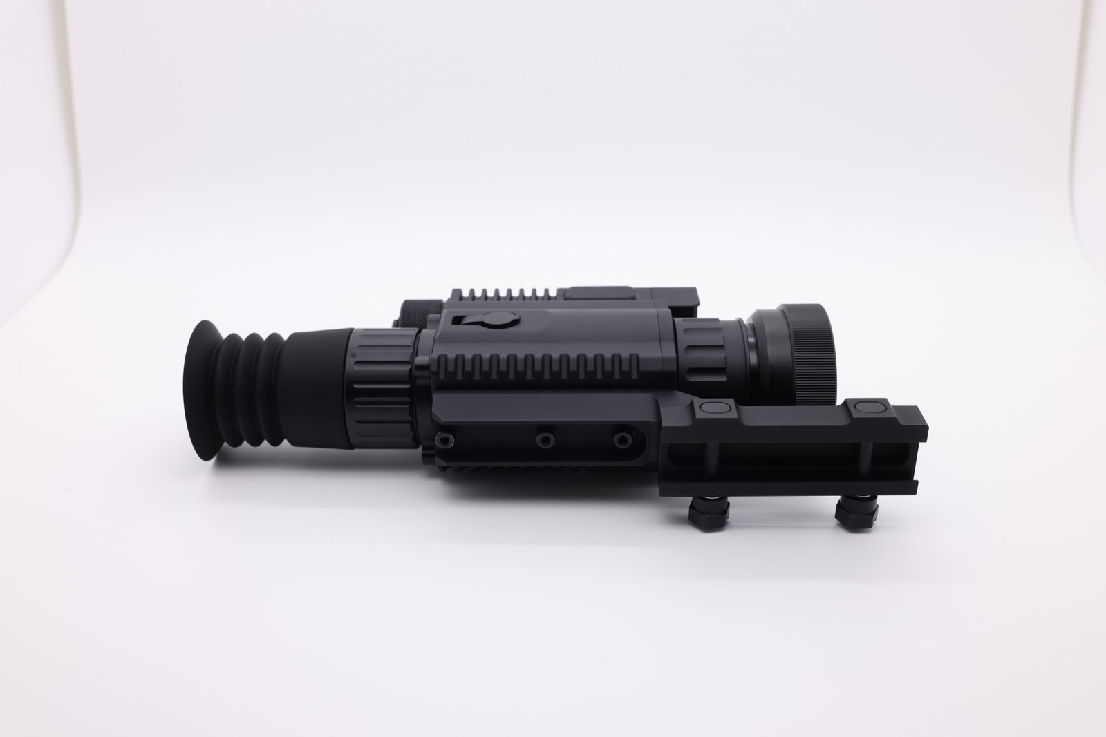
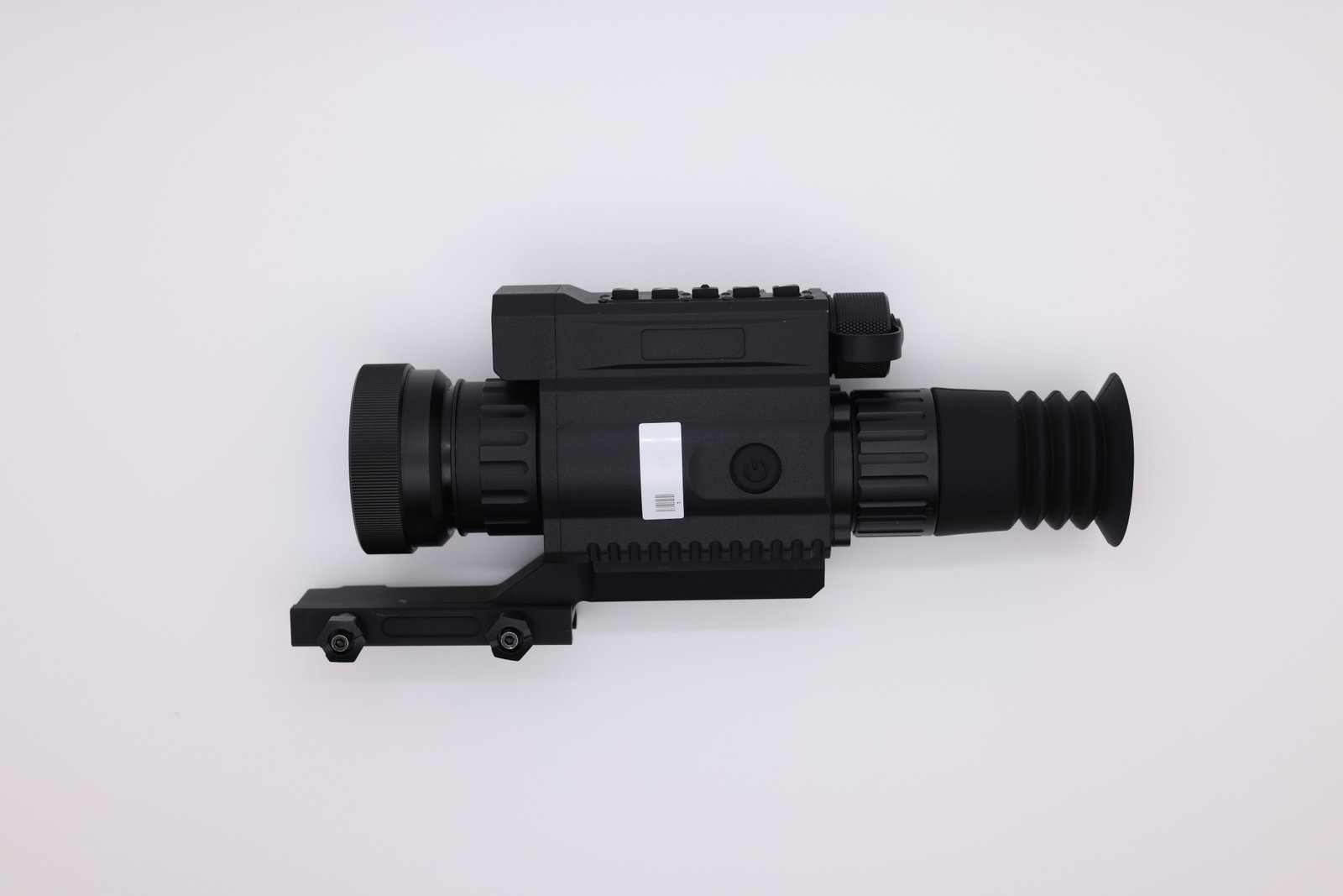
The infrared sight consists of an infrared lens, a laser rangefinder, an infrared uncooled detector, a mid-shell assembly, eyepiece, a battery, a gun connecting seat, etc., as shown in Figure 1
The infrared sight is mounted to a rifle through the gun connecting seat; The infrared radiation of the target is focused on the sensitive element of the infrared uncooled focal plane detector through the infrared objective component, and after the thermoelectric conversion, the processed electrical signal is generated; The movement circuit board pretreats the electrical signal and converts it into digital image signal; Then the digital image signal for non-uniformity correction, blind element replacement, image enhancement, brightness contrast adjustment and other image processing; After the image processing board superimposed menu, interface and other information on the processed image, it can realize compression storage or WiFi transmission, target recognition and other functions, which could transmit the relevant information to the eyepiece display, or transmit it to the mobile phone, glasses and other wearable devices display through WiFi to assist the shooter to complete the viewing.
| Serial Number | Indicator items | Parameters | Remarks |
|---|---|---|---|
| 1 | Infrared detector | 384 x 512 @ 12 microns | Optional |
| 2 | 640 x 512 @ 12 microns | Optional | |
| 3 | Working band | 8 microns ~ 14 microns | |
| 4 | Infrared lens (384) | F=1.0, f=25mm | Standard |
| 5 | F=1.0, f=35mm | Optional | |
| 6 | Infrared lens (640) | F=1.0, f=35mm | Standard |
| 7 | F=1.2, f=50mm | Optional | |
| 8 | F=1.2, f=75mm | Optional | |
| 9 | Identification distance (384) | 25mm: ≥400m for person; ≥800m for vehicles | |
| 10 | 35mm: ≥600m for person; ≥1200m for vehicles |
||
| 11 | Identification distance (640) | 35mm: ≥600m for person; ≥1200m for vehicles |
|
| 12 | 50mm: ≥800m for person; ≥1600m for vehicles | ||
| 13 | 75mm: ≥1300m for person; ≥2400m for vehicles | ||
| 14 | Field of view (384) | 25mm: 10.5° x 7.9° | |
| 15 | 35mm: 7.5° x 5.7° | ||
| 16 | Field of view (640) | 35mm: 12.5° x 10° | |
| 17 | 50mm: 8.8° x 7.0° | ||
| 18 | 75mm: 5.9° x 4.7° | Laser ranging is not supported | |
| 19 | Laser Ranging | ≥800m | Optional |
| 20 | Imaging range | 5m~∞ | |
| 21 | Visibility | -5SD ~+5SD | |
| 22 | Weight (including connecting base, battery) | ≤800kg | |
| 23 | Power supply method | 2 CR 123A rechargeable batteries or power banks | Optional |
| 24 | 1 18650 rechargeable battery or power bank | Optional | |
| 25 | Continuous working hours | ≥4h | |
| 26 | Storage capacity | 64G standard, optional: 128G, 256G | |
| 27 | WiFi | ≥3m | |
| 28 | Operating temperature | -20℃ ~ +50℃ | |
| 29 | Impact | 500g, 1ms | Optional |
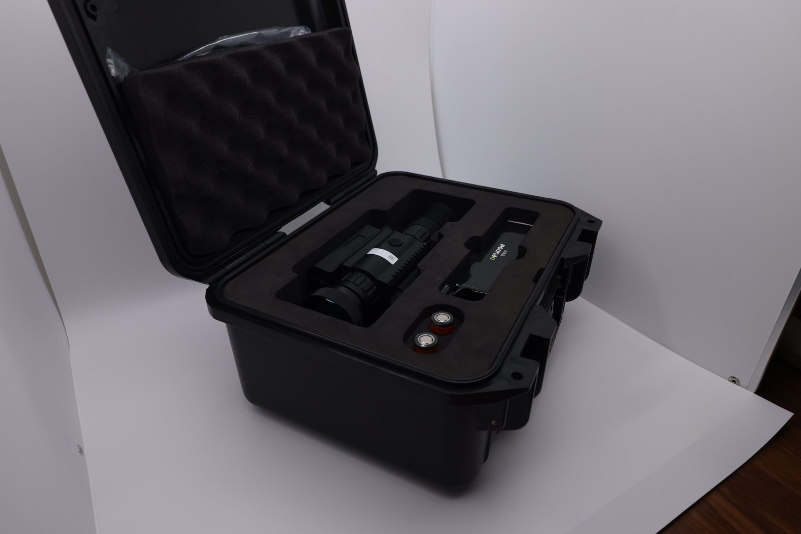
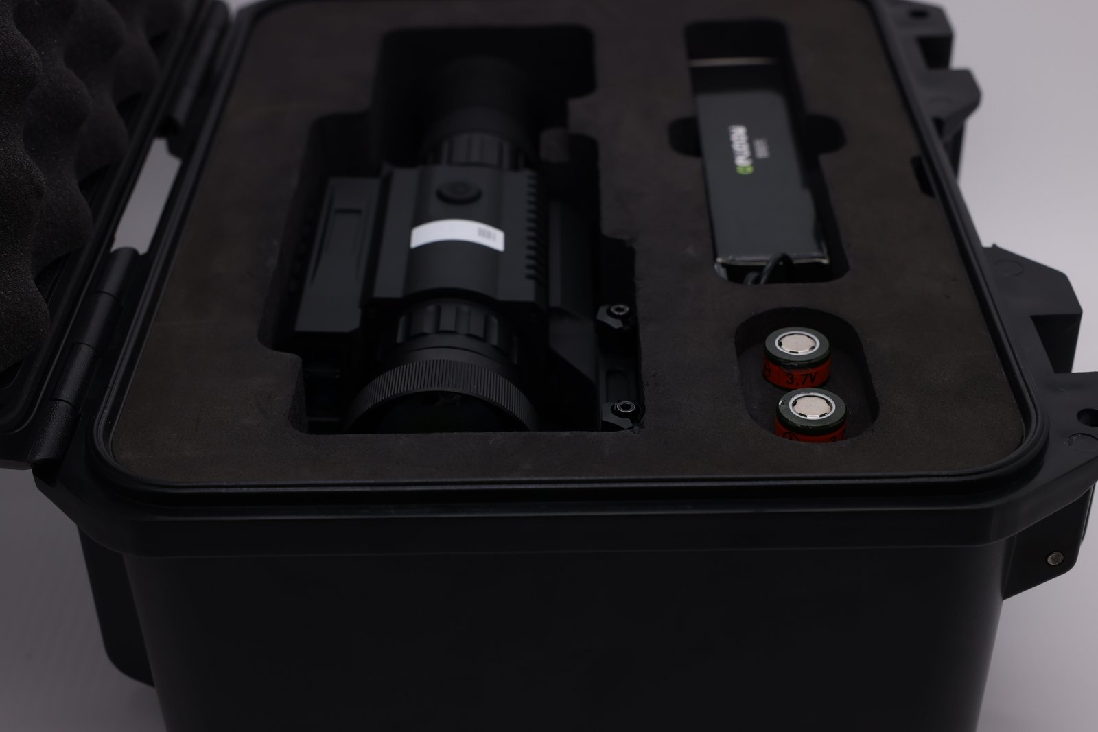
The infrared sight is delivered with a plastic packing case or a paper packing case for the user to choose from.
| No. | Name | Quantity | Remarks | |
|---|---|---|---|---|
| 1 | Products | Infrared sight | 1 set | Includes connecting seat |
| 2 | Battery (18650) | 2 units | ||
| 4 | Carrying Bags | one | ||
| 5 | Packing Box | 1 | Plastic or paper | |
| 6 | Get accessories and tools | Charger | 1 | |
| 7 | Data cable | 1 | ||
| 8 | Random Files | Packing list | part | |
| 9 | Product certificate | 1 copy | ||
| 10 | Use maintenance instructions | 1 copy |
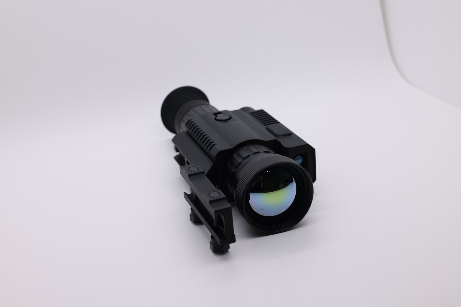
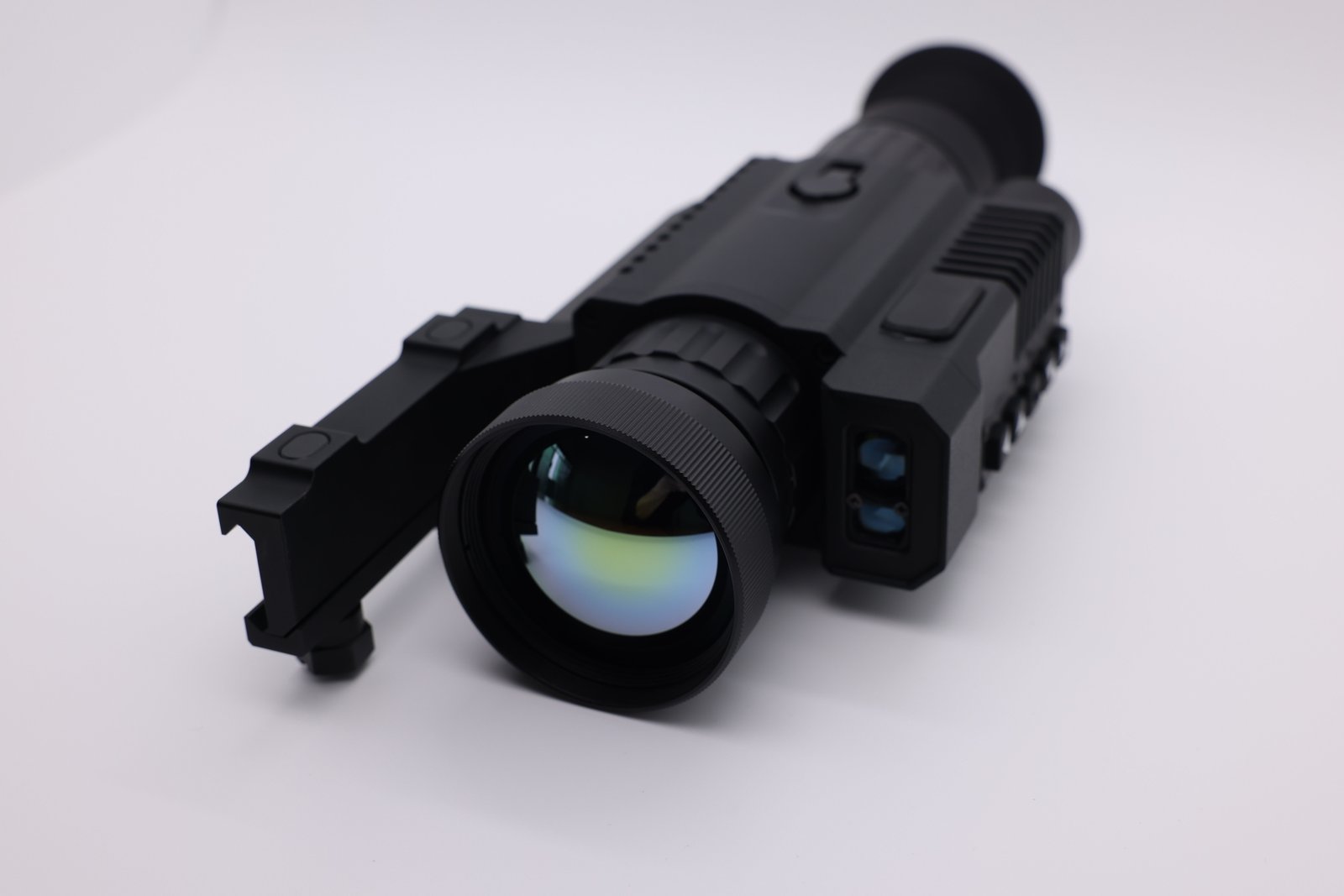
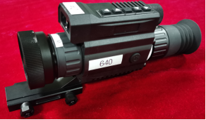
The components of the body of the infrared sight are introduced as follows:
Figure 2 Composition of each part of the body of the infrared sight
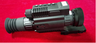 1.Objective lens assembly;
2.Laser rangefinder;
3 multi-function button.;
4. Eyepiece;
5. Power key;
6. Connecting seat;
7. Battery cover;
8. Middle shell assembly;
9. External connector.
1.Objective lens assembly;
2.Laser rangefinder;
3 multi-function button.;
4. Eyepiece;
5. Power key;
6. Connecting seat;
7. Battery cover;
8. Middle shell assembly;
9. External connector.
Before installing the battery, check whether the infrared sight is off through the eyepiece, observe the direction of the eyepiece, turn counterclockwise to loosen the battery compartment cap, put the positive electrode of the battery into the battery compartment, and then turn clockwise to lock the battery compartment cap to complete the battery installation. In the case of damp or rain, to avoid device failure caused by water in the battery compartment, ensure that the cover of the battery compartment is completely closed after loading the battery compartment.
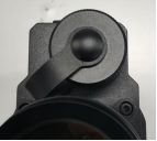
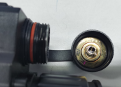
Figure 3 Battery loading diagram
The infrared sight has the function of battery polarity reverse connection protection, when the battery is inverted, the infrared sight will not be turned on.
Before opening the battery compartment cover, make sure the infrared sight is turned off!
Before loading the infrared sight card, first confirm that the infrared sight gun connecting seat and the gun base interface match, and carefully clean both with a brush, otherwise it will not be able to guarantee the accuracy of the card.
Place the sight on the Picatinki seat of the gun and lock the nut clockwise; To withdraw, loosen the lock nut counterclockwise and remove the scope from the firearm.
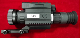
Figure 4 Infrared sight mounting clip
After the infrared sight is locked to the gun base, it needs to be calibrated to fully fit the gun. For calibration operations, see section 6.5.4.6.
Note
When removing the infrared sight, the handle should be loosened until the infrared sight can be removed smoothly, and there is no need to loosen to the limit position to avoid the hand screw nail stuck or other unknown situations!
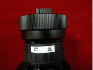
In the direction of observation, counterclockwise is the far-focus, suitable for observing distant targets, and clockwise is the near-focus, suitable for observing near targets. According to the different distance of the target, the user needs to manually adjust the lens focal length to make the image clear.
During the viewing process, the eyepiece can be rotated by the viewing adjustment handwheel in direction 2 to compensate the viewing. Clockwise rotation is positive, suitable for far-sighted people, counterclockwise rotation is negative, suitable for nearsighted people, the direction is marked on the case. When used, it can be adjusted according to the user's personal visual degree.
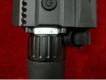
FIG. 6 Schematic diagram of the use of the handwheel for visual adjustment
The control of the infrared scope is completed by a power key and a multi-function knob, as shown in Figure 12. Their respective functions and usage are described as follows:
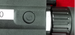 FIG. 7 Power key illustration
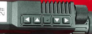 FIG. 8 Multi-function key illustration
1. Top; 2. Right; 3. Middle; 4. Left; 5. Down.
FIG. 8 Multi-function key illustration
1. Top; 2. Right; 3. Middle; 4. Left; 5. Down.
Serial number |
Key name |
Main function |
Remarks |
1 |
Power button |
Long press to power on, long press to bring up the Shutdown dialog box, Menu Back/Exit, Laser |
|
2 |
Up. |
Short press to take a picture, long press to record, and move the score up |
|
3 |
Under the |
Infrared mode switch, division move down |
|
4 |
On the left |
Electronic zoom out, menu shift left, Division shift left |
|
5 |
right |
Electronic magnification, menu shift right, Division shift right |
|
6 |
In the |
Popup menu, confirm |
|
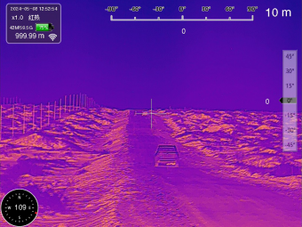
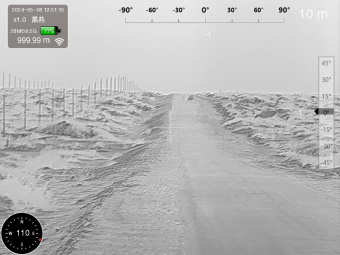
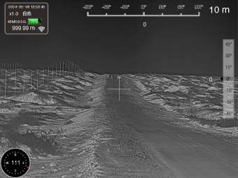
Make sure that the battery is installed, hold down the power button for about 1s, the eyepiece will light up, about 10s after the initialization is completed, you can observe the image display interface.
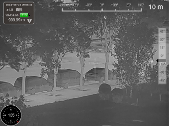
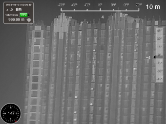
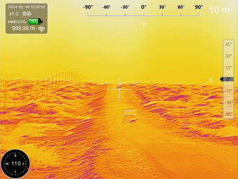
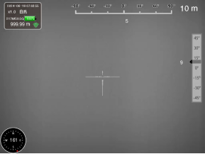 Figure 9 Interface display
According to the numbers 1 to 5 in the figure, introduce the meaning of the information displayed in each area in turn: 1. Information bar, including date, time, magnification, polarity, memory capacity, power, ranging, WiFi status, etc.; 2. Roll Angle; 3. Pitch Angle; 4. Division; 5. Azimuth.
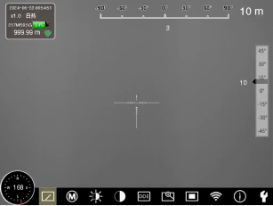 Figure 10 Level 1 menu diagram
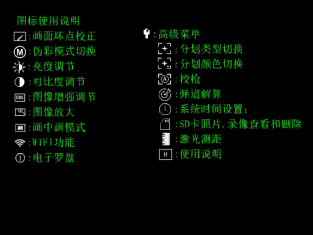
Advanced Menu
Figure 10 Level 1 menu diagram
Advanced Menu
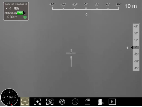 Figure 11 Advanced Menu